
ENGINEERED FOR THE PROCESS
Rotary Airlock Valve
Custom rotary airlock valves for powder feeding, discharge and pressure isolation in pneumatic conveying and dust collection systems.
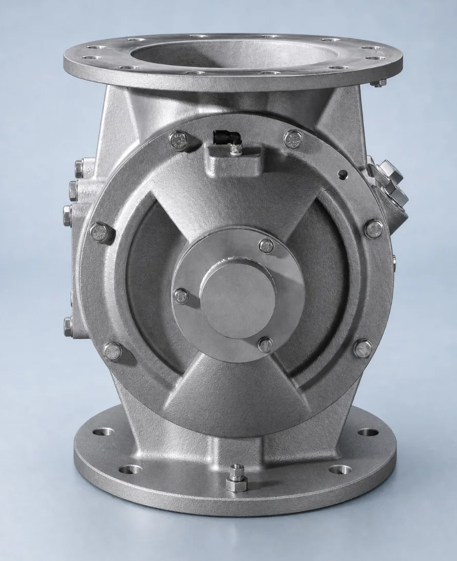
What a rotary airlock valve does
A rotary airlock valve transfers powder or granules between two parts of a process while restricting the flow of air across the pressure boundary. As the rotor turns, material fills the pockets at the inlet and discharges at the outlet. The valve can meter solids, empty a hopper or dust collector, and feed a pneumatic conveying line.
An airlock is not an absolute zero-leak shutoff valve. Leakage depends on pressure differential, operating temperature, rotor-to-body clearance, speed, wear and product buildup. These conditions must be reviewed together before the valve size and internal configuration are fixed.
Typical duties
- Discharge below dust collectors, cyclones, filters and silos
- Controlled feeding into pneumatic conveying systems
- Metering at hopper and process-equipment outlets
- Pressure isolation between connected process zones
Configuration directions
- Carbon steel, stainless steel contact parts or full stainless steel
- Round, square or custom inlet and outlet interfaces
- Rotor, clearance and end-seal arrangements selected for the material
- Drive speed, torque and orientation matched to duty and installation access
CONFIGURATION GUIDE
Choose the configuration by process duty
The same flange size can require a different valve when pressure, temperature, material behavior or cleaning requirements change. Use the process duty—not only the connection size—to narrow the configuration.
Gravity discharge and general airlock duty
A drop-through rotary airlock is the normal starting point for discharge below filters, cyclones and hoppers. Confirm the pressure differential and acceptable leakage before selecting rotor clearance and speed.
Positive-pressure pipeline feeding
When material must enter a conveying line directly, review a blow-through rotary valve. Conveying air, venting and product velocity affect whether this arrangement is suitable.
Food, corrosion or frequent cleaning
Use a stainless steel rotary valve direction when product-contact materials, corrosion resistance or cleaning procedures require it. Surface finish and access should be specified rather than assumed.
Abrasive material or continuous duty
Review a heavy-duty rotary valve together with wear locations, duty cycle and maintenance targets. A harder surface alone does not remove the need to control clearance as components wear.
Unusual interface or replacement project
A customized rotary valve can be configured around an existing flange, center height, drive orientation or installed model. Supply a drawing or measured interface instead of relying on a model name alone.
Sticky or cohesive material
For pockets that do not empty consistently, review the sticky-powder configuration guide. Upstream hopper bridging and valve-pocket adhesion are different failure modes and may need different corrections.
QUOTATION INPUTS
Information needed for a comparable quotation
- Material name, particle characteristics and bulk density
- Required mass flow or volumetric capacity
- Normal and maximum temperature
- Pressure at the inlet and outlet, or pressure differential
- Flange drawing, available installation height and drive orientation
- Motor voltage, frequency, hazardous-area requirement if applicable
- Duty cycle, cleaning method and expected maintenance interval
Use the capacity calculation guide, dimension checklist and selection guide to prepare the data. For a replacement, add the existing nameplate, model and interface dimensions.
TECHNICAL FAQ
Rotary airlock valve questions
What is the difference between a rotary airlock valve and a rotary feeder?
The terms overlap. An airlock duty places more emphasis on limiting air leakage across a pressure differential, while a feeder duty places more emphasis on controlled solids flow. The actual rotor, clearance, speed and sealing arrangement must still be checked for the process.
What controls air leakage through a rotary airlock valve?
Pressure differential, rotor-to-body clearance, temperature, rotor speed, venting, product buildup and wear all affect leakage. A rotary airlock reduces leakage but should not be treated as an absolute zero-leak shutoff valve.
How should a rotary airlock valve be sized?
Size should be based on required mass or volumetric flow, bulk density, rotor displacement, speed and realistic filling efficiency. Inlet size alone is not enough to predict capacity.